-40%
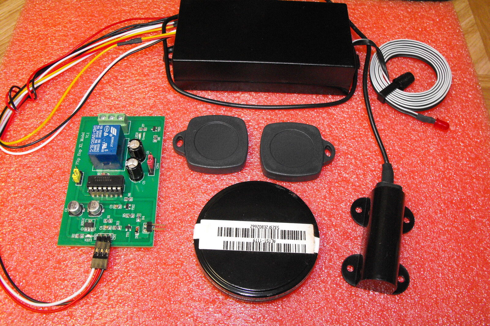
RFID Reader transponder access control 3 mode relay momentery and flip flop
$ 8.97
- Description
- Size Guide
Description
unit comes with a 3 mode electronic relay,momentary
or
momentary
delay or flip flop, ready to go !!!!
www.rfidadvance.com
These
are being used to prevent theft of autos, provide increase security in buildings, to operate electronic gates, garage doors, computers,etc. Consists of a small key fob that is totally self contained (no moving parts or batteries) and a proximity sensor and associated receiver circuit box. When the key fob is brought within 3 inches of the sensor, the unique date incoded in the key fob is transfered to the sensor-receiver, activating whatever device-relay, solenoid, light, locks, etc.- that you have connected to the receiver. These are brand new units consisting of two key fobs, a master programer key in a sealed container, and a receiver box with sensor. The receiver is very sophisticated and can not be activated except by the key fobs that come with it. If someone steals one of the key fobs, you may program a new code with the master programer key fob into a remaining fob so that the stolen one will no longer work. The coding of new keys does not use a compute and can easily be completed in a few second period. The system is absolutely amazing. The reciever operates on 12 VDC Details: The key fob is completely waterproof, and crunch resistant. Size:l.4" square and is meant to be attached to your keychain and has a recessed circle to allow you to place a custom label (if desired). The sensor is about 2.1" x 1.3" and is attached by 20" cable to the 4 1/8" x 2 1/8" receiver box. The sensor can be mounted in wood, behind glass or plastic and still function perfectly. The sophisticated receiver uses 6 ICs and have 3.3V OUT PUT WHEN TRRIGER . when the correct key fob is brought within 3 inches of the sensor. THE relay will close , and when key removed from sensor relay will open.This new technology has thousands of applications. As soon as you buy one of these units you'll want to purchase more as you realize all the different ways it can automate or control security tasks. Brand new with complete instructions,UNIT WILL COME WITH COMPLET WIRING DIAGRAM.
This is ideal for the electronic hobbyist wishing to build a simple electronic high security door locking system.
The kit consists of an RFID reader coupled with a 125KHz antenna. The kit comes with two RFID keyfob tags. Extra tags are available in two formats, Keyfob or Disc. The Keyfob as it's name suggests can be attached to a keyring, whilst the Disc can be put into a wallet or purse.
The read range is 50mm - 75mm.
The tags have unique serial numbers allowing only tags which have been programmed in to the RFID reader by the master programming fob to activate the reader output.
The reader has a 3.3v output which is active for as long as the keyfob is held in front of the RFID reader's antenna.
This output will drive a relay which in turn unlocks a door latch.
The reader unit runs from 9V to 15V DC. You can program up to 25 RFID keyfobs per reader.
Dual Mode Relay Board
See the attached block diagram of the “Dual Mode Relay Board” (referred to as DMRB).
This board can be used alone or together with” RFID Access System” ( Antenna/CPU Box , Wiring Harness, Master Key, 2 Key FOB’s)
DMRB inputs ( left side)
SIG ( signal) pin-“ H” ( digital HIGH)- 3v to 12VDC ,” L” ( digital Low)-0VDC
Vcc pin-
+12VDC
Gnd pin-
system ground
“Power ON” LED ( Left side of DMRB)- is “lit” to indicate that the DMRB is receiving 12VDC ( Vcc pin) and also system ground is connected ( Vcc pin).
The EN LED ( Right side of the DMRB) indicated that the relay on the DMRB is ACTIVE.
OPERATION
The DRB can operate in 2 modes. Momentary Mode( jumper pins 1&2 connected) or Flip Flip/Latch Mode(jumper pins 2&3 –connected).
Momentary Mode
In this mode the relay on the DMRB goes into the “Active State”
( EN LED becomes “lit”) ONLY as long as the user holds the the Key BOF close to the Antenna ( OR- as soon the SIG input goes “H”).
As soon as the Key FOB is removed from the vicinity of the Antenna( OR-as soon as the SIG input goes “L”)- the relay returns to the “Inactive State” ( EN LED is “dark”).
Flip Flop/ Latch Mode
In this mode the relay goes into and
STAYS ( Latched) in its new state (either ACTIVE
or INACTIVE)
AFTER
the Key FOB is “brought close and is removed from the antenna” ( OR the SIG input “H”and back to “L”).
Every time that the Key FOB is “brought close to the Antenna and then removed” ( OR-as soon as the SIG input goes “H”and the back to “L”) the relay on the DMRB goes into and STAYS in the “opposite state”
( Flip Flop). The relay on the DMRB STAYS ( Latched)
in its “current state” until the Key FOB is again “brought close to the Antenna and removed” ( Or the SIG input goes “H” and back to “L”).
look at item
372375828834
if you need more key fobs


